The Main PCB
This is the most complicated and delicate board of the whole robot, as it contains the main microcontroller and a lot of small-pitch connectors.
Take your time with this one, and make sure to follow the instructions carefully to avoid damaging the board or the components.
As this board is pretty big, the assembly process will be split in 7 parts. Starting with soldering the board's surface-mount connectors and components, and then the through-hole ones.
Solder each section
If you have a small hot plate, it may be easier to solder the SMD components between each section, not after completing all of them.
1 - The audio management
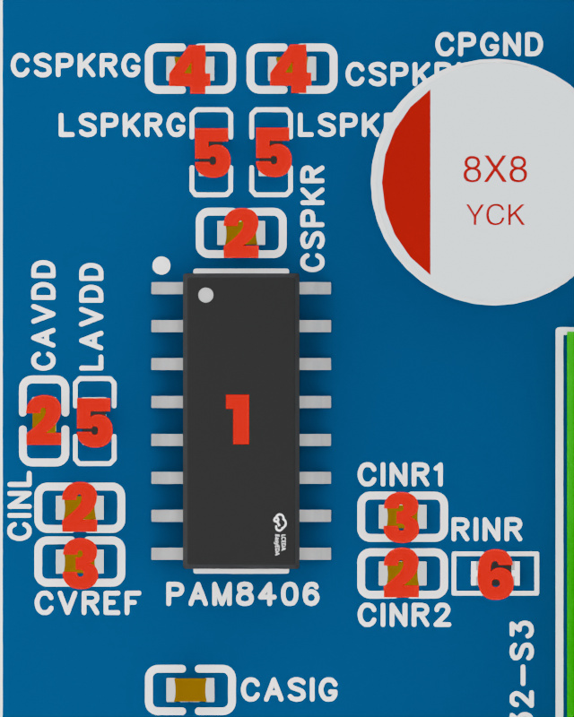
We'll start with the audio section, which is located on the left side of the board. This section contains the PAM8406 audio chip as well as filtering and power management components.
For this section, you'll need :
| ID | Component | Description | Quantity |
|---|---|---|---|
| 1 | PAM8406 Audio Chip | Main audio processing chip | 1 |
| 2 | 0603 100nF Capacitor | Decoupling capacitor | 4 |
| 3 | 0603 1uF Capacitor | Decoupling capacitor | 2 |
| 4 | 0603 220pF Capacitor | Decoupling capacitor | 2 |
| 5 | 0603 Ferrite Bead | EMI filtering component | 3 |
| 6 | 0603 1kΩ Resistor | Low-pass filter resistor | 1 |
2 - The USB connexion
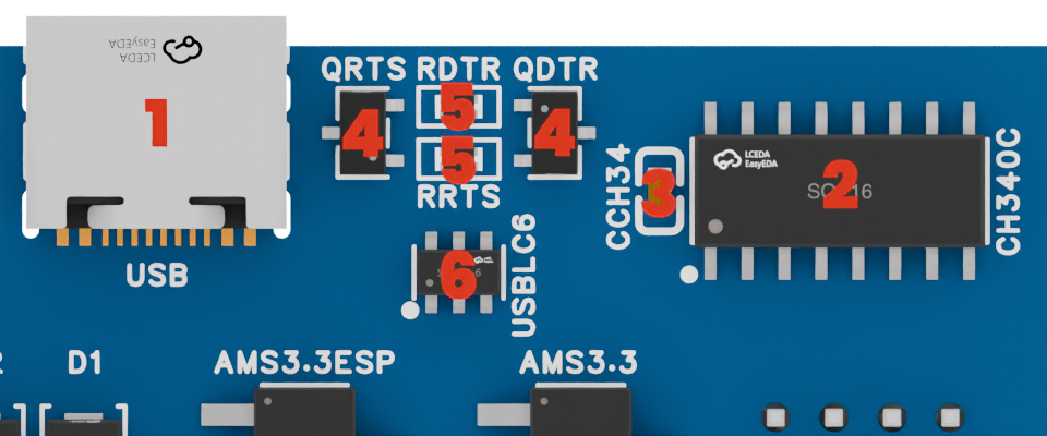
The USB section is located on the top right of the board, and it contains the USB-C connector as well as the necessary components for programming and communication with the ESP32-S3.
For this section, you'll need :
| ID | Component | Description | Quantity |
|---|---|---|---|
| 1 | USB-C Connector | Main USB connector for programming | 1 |
| 2 | CH340C USB-to-Serial Chip | USB-to-Serial converter chip | 1 |
| 3 | 0603 10uF Capacitor | Decoupling capacitor | 1 |
| 4 | SOT-23-3L BJT Transistor | Used for programming sequence | 2 |
| 5 | 0603 10kΩ Resistor | Resistors for programming | 2 |
| 6 | SOT-23-6 USB Protection IC | ESD protection for USB lines | 1 |
USB Connector
The USB-C connector is really fragile when its 4 housing pins are not soldered to the board, and moving it after soldering its connection pins can break the solder joints or the PCB traces.
Be careful with it until it is securely soldered to the board in the step 6.
3 - The camera components
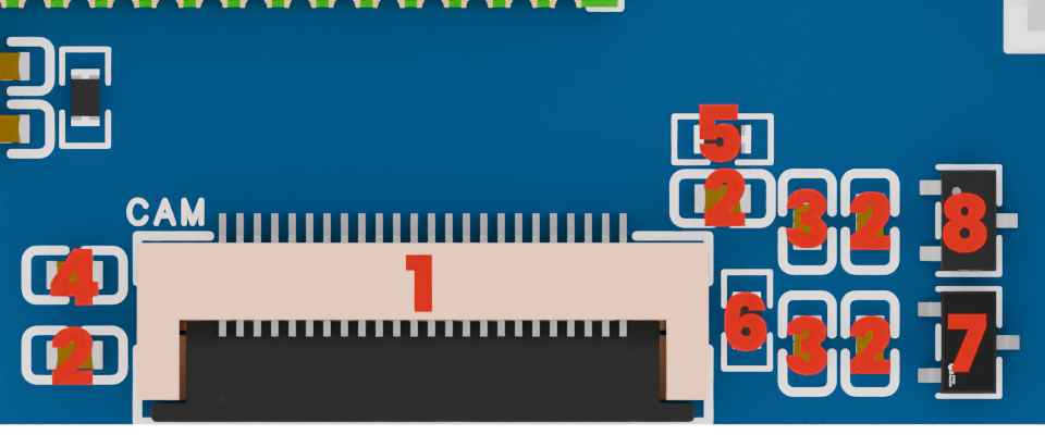
The camera section is located on the bottom center of the board, and it contains all the components necessary for powering and connecting the camera module to the board.
This section is particularly delicate, as it contains a lot of small components and a fine-pitch FPC connector.
For this section, you'll need :
| ID | Component | Description | Quantity |
|---|---|---|---|
| 1 | FPC 24-pin Connector | Camera connector | 1 |
| 2 | 0603 100nF Capacitor | Decoupling capacitor | 4 |
| 3 | 0603 10uF Capacitor | Decoupling capacitor | 2 |
| 4 | 0603 15pF Capacitor | Decoupling capacitor | 1 |
| 5 | 0603 4.7kΩ Resistor | Pull-up resistor | 1 |
| 6 | 0603 1kΩ Resistor | Pull-down resistor | 1 |
| 7 | SOT-23-3L 1.2V LDO | Digital supply for camera | 1 |
| 8 | SOT-23-3L 2.8V LDO | Analog supply for camera | 1 |
4 - The power management
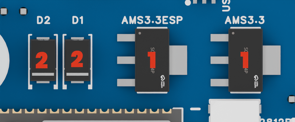
The power management section is located under the USB connector, and contains a few components for power supply management.
For this section, you'll need :
| ID | Component | Description | Quantity |
|---|---|---|---|
| 1 | SOT-223 3.3V LDO | Main power supply | 2 |
| 2 | SMA-L4.3 Diode | USB vs Battery selection | 2 |
Diode orientation
The SMA-L4.3 diodes have a cathode marking on one side (a little bar), make sure to place them in the correct orientation as shown on the silkscreen, otherwise the power supply selection won't work.
5 - The ESP32-S3 and LED
The main section of the board is located in the center, and contains the ESP32-S3 microcontroller as well as the RGB status LED for debugging.
For this section, you'll need :
| ID | Component | Description | Quantity |
|---|---|---|---|
| 1 | ESP32-S3 N16R8 | Main microcontroller | 1 |
| 2 | XL550 WS2812B LED | RGB status LED | 1 |
| 3 | 0603 2.2kΩ Resistor | I2C pull-up resistor | 4 |
| 4 | 0603 10kΩ Resistor | Enable pull-up resistor | 1 |
| 5 | 0603 100nF Capacitor | Decoupling capacitor | 1 |
| 6 | 0603 10uF Capacitor | Decoupling capacitor | 1 |
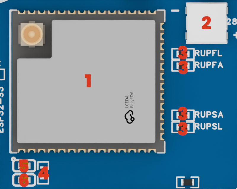
Wiring problems on V1.0
Check your PCB version on the back of the board. If the version is 1.0, you'll have to make a small modification to the board after soldering the ESP32-S3.
The V1.0 version of the board uses the GPIO46 as one the of two I2C's SCL lines, which means this line is pulled up to 3.3V through a 2.2kΩ resistor. However, the ESP32-S3's GPIO46 is a strapping pin that is used to select the boot mode of the chip. This prevents it from switching to download mode when you try to flash the firmware.
To fix this issue (already applied on the V1.1 version of the board) :
- Cut the trace between the
GPIO46pin and theRUPSL2.2kΩ resistor, as well as the trace between the GPIO48 and theLEDusing a sharp knife or a rotary tool; - Solder a first wire between the
GPIO46pin and the data line of theLED; - Solder a second wire between the
GPIO48pin and the left side of theRUPSL2.2kΩ resistor (the side that is not connected to the 3.3V line).
6 - The back connectors
Now that all the SMD components are soldered, we can move on to the through-hole ones. But before doing anything, we'll solder the USB-C connector's housing pins, to make sure it is securely attached to the board.
Soldering the USB-C connector
Flip the board to access the back of the USB-C connector. Push the connector flush against the board, and solder the 4 housing pins on the back of the board.
Use a little bit of solder flux to make sure the solder flows well, and be careful not to use too much heat or pressure on the connector to avoid damaging it or the PCB.
Soldering the other connectors
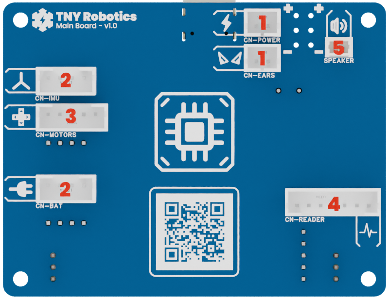
The board contains 7 other JST connectors on the back for power supply and communication with the rest of the robot. These connectors are pretty big and easy to solder, but make sure to align them properly.
For this step, you'll need :
| ID | Connector | Description | Quantity |
|---|---|---|---|
| 1 | JST PH 2-pin | Power supply & Ears motors | 2 |
| 2 | JST PH 4-pin | IMU & Plug PCB connectors | 2 |
| 3 | JST PH 5-pin | Motor Driver connector | 1 |
| 4 | JST PH 7-pin | Analog Reader connector | 1 |
| 5 | 1.25 mm 2-pin | Speaker connector | 1 |
7 - The front connectors
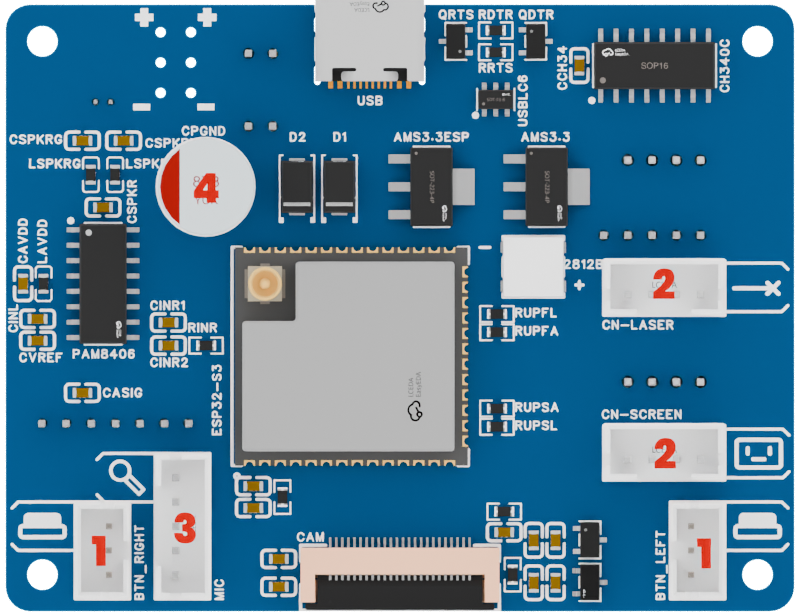
Moving on the front of the board, we have 5 more JST connectors to solder, and a 470uF capacitor for the speaker power supply.
make sure to solder the capacitor in the correct orientation, as it is polarized.
For this step, you'll need :
| ID | Connector | Description | Quantity |
|---|---|---|---|
| 1 | JST PH 3-pin | Left & Right buttons | 2 |
| 2 | JST PH 4-pin | Laser & Screen connectors | 2 |
| 3 | JST PH 5-pin | I2S Microphone connector | 1 |
| 4 | 470uF Capacitor | Speaker capacitor | 1 |
Final inspection
After soldering all the components, inspect the PCB carefully to ensure that all joints are solid and there are no solder bridges or cold joints. Use a magnifying glass if necessary to check for any issues.
If you have a multimeter, you can also check for continuity between the pins of the connectors and the corresponding pads on the PCB to ensure that everything is properly connected.
If all the checks are good, you can also try powering the board on for the first time to see if your PC recognizes the USB device.
All good ? Well, congratulations! You've just soldered the most complicated PCB of the whole robot!
Let's do a bit more soldering now, but to prepare all the other components and boards !