Main board
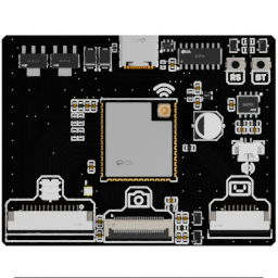
The main board contains the robot's central processing and control electronics. It is the point where firmware execution connects to the hardware buses and higher-level peripherals.
Useful links
Go to the Assembly Step
Go to the assembly step where the analog reader is being installed.
Board reference
Role
- run or host the main controller electronics;
- connect the firmware to the torso buses and peripherals;
- expose the interfaces required by the camera, display, audio, and sensors.
Location
The main board is installed in the head assembly.
Main topics
- processor and support circuitry;
- two independent 3.3 V LDOs;
- USB-C serial connection to the ESP32-S3;
- 14-pin FPC connection to the backbone;
- camera connection;
- audio amplifier and speaker connection;
- buses for the IMU, analog reader, motor driver, and backbone extension port;
- revision-specific pinout.
Separate 3.3 V rails
One LDO powers the ESP32-S3 and camera. A second LDO powers the IMU, analog reader, motor driver, and the backbone's extension-port electronics.
This separation helps keep the main CPU and its web portal alive if a short circuit occurs elsewhere in the robot's peripheral electronics.
USB-C and audio
The USB-C port exposes the ESP32-S3 serial connection for direct control, debugging, and firmware work.
An audio amplifier connects to the head speaker, allowing the robot to produce sounds, play music, or speak.
The main board connects to the backbone through a 14-pin FPC with a 1 mm pitch.
Status LED
The main board has an addressable LED that can report its own state independently, for example by turning red when its diagnostic checks fail.
Pinout
Add a photo of the board with numbered pins here, followed by the completed table:
| Pin | Connector | Signal | Destination | Notes |
|---|---|---|---|---|
| 1 | To be numbered | To be completed | To be completed | To be completed |
The board's software-facing behavior is described in Hardware drivers.