IMU board
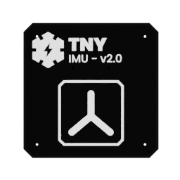
The IMU board carries the six-axis inertial sensor used to estimate the robot's orientation and movement.
Useful links
Go to the Assembly Step
Go to the assembly step where the analog reader is being installed.
Board reference
Role
- host the inertial measurement unit;
- connect acceleration and angular-velocity data to the controller;
- provide the bus and power connections required by the selected sensor.
Location
The board is installed above the motor-power corridor, close to the center of the robot but far enough away to reduce electrical interference from the motors.
Main topics
- six-axis IMU;
primaryI2C bus connection;- shared bus with the motor driver;
- power, ground, and mounting orientation;
- revision-specific pinout.
Primary I2C bus
The IMU uses the primary I2C bus, shared with the motor driver. Keeping these latency-sensitive devices on the primary bus helps the 200 Hz control loop receive orientation and motor-related data with as little delay as possible.
Status LED
The IMU board has an addressable LED that can report its diagnostic and operating state independently.
Pinout
Add a photo of the board with numbered pins here, followed by the completed table:
| Pin | Connector or header | Signal | Destination | Notes |
|---|---|---|---|---|
| 1 | To be numbered | To be completed | To be completed | To be completed |
The firmware supports different IMU implementations behind one abstraction. See Hardware abstraction and Locomotion.