Buck converter
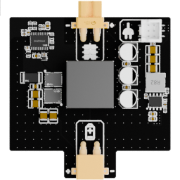
The buck converter creates the two main regulated voltage buses used by the robot from the battery supply.
Useful links
Go to the Assembly Step
Go to the assembly step where the analog reader is being installed.
Board reference
Role
- generate a
6.7 V,20 Abus for the motors; - generate a
5 V,3 Amaximum bus for the rest of the electronics; - route each bus to the board that needs it.
Output buses
| Bus | Maximum output | Destination |
|---|---|---|
| Motor bus | 6.7 V, 20 A | Directly to the backbone through an XT30 connection |
| Logic bus | 5 V, 3 A maximum | To the extension board, then back to the backbone |
The 5 V bus deliberately passes through the extension board before reaching the backbone. This avoids routing the logic supply through the motor-power corridor, where motor activity can create significant electrical noise.
Pinout
Add a photo of the board with numbered pins here, followed by the completed table:
| Pin | Connector | Signal | Voltage or current | Notes |
|---|---|---|---|---|
| 1 | To be numbered | To be completed | To be completed | To be completed |
Main topics
- input and output voltage domains;
- current capacity and thermal considerations;
- input and output connectors;
- relationship with the power board and backbone;
- revision-specific pinout.
Power conversion is part of the system architecture
The buck converter should be understood together with the power board and the global power diagram. It is not an isolated supply for one single component.
For the global power path, see Electrical architecture.