Extension board
The extension board exposes an expansion port on the back of the TNY-360. It gives external hardware a way to connect to the robot without requiring modifications to the main body or directly accessing the internal boards.
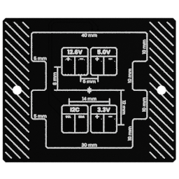
The port is intended for addons such as:
- a LiDAR sensor;
- a robotic arm;
- a Raspberry Pi or another companion computer;
- future sensors and custom hardware.
Useful links
Go to the Assembly Step
Go to the assembly step where the analog reader is being installed.
Board role
The extension board acts as the interface between an external addon and the robot's internal electrical system.
It provides a defined place to connect an addon while keeping the internal wiring and the main control electronics protected inside the robot.
Location
The extension board is located in the rear of the robot and exposes its connection point through the back of the body.
This location makes it possible to mount or connect an addon without routing a cable through the head or opening the main torso assembly.
Addon integration
An addon connected through this board may need one or more of the following:
- regulated power;
- ground;
- a communication bus;
- control or status signals;
- a mechanical mounting solution.
The available signals and power depend on the board revision and the intended addon. Always check the corresponding connector pinout before connecting external hardware.
Available resources
The extension board exposes four resources:
| Resource | Source | Continuous limit | Intended use |
|---|---|---|---|
| Battery bus | Power board | 4 A | Addons that need the raw 3S battery range |
| 5 V bus | Buck converter | 1 A | Addons requiring regulated 5 V |
| 3.3 V bus | Local LDO | 1 A | Low-voltage modules and sensors |
I2C secondary | Backbone | — | Communication with external modules |
The battery bus can range from 11.1 V to 12.6 V depending on the state of the 3S Li-Po battery.
Connections
The board connects to the buck converter through a 6-pin JST-PHD cable. This connection carries the battery bus and the 5 V bus while allowing the extension board to provide a useful current margin for external hardware.
It connects to the backbone through a 4-position JST-PH cable. This connection carries the 5 V supply for the rest of the robot and the secondary I2C bus.
Pinout
Add a photo of the board with numbered pins here, followed by the completed table:
| Pin | Connector | Signal | Voltage or protocol | Notes |
|---|---|---|---|---|
| 1 | To be numbered | To be completed | To be completed | To be completed |
The pinout must be checked against the board revision before an addon is connected.
Check compatibility before connecting an addon
The extension port is not a universal connector. Verify its voltage levels, available current, signal assignments, and connector orientation before connecting a LiDAR, robotic arm, Raspberry Pi, or custom board.
Relationship with the firmware
The extension board provides the electrical access point, but the firmware or an external companion computer must still know how to communicate with the connected addon.
Depending on the hardware and the future software support, an addon may be handled by:
- a dedicated firmware driver;
- a network-connected companion computer;
- a user application using an exposed communication bus;
- a future extension API.
The electrical design is described in Electrical architecture, while the physical connections between boards are documented in the PCB ecosystem.