Motor driver
The motor driver connects the control electronics to the robot's actuators. It carries motor commands, supplies the relevant power path, and returns feedback needed by the control loop.
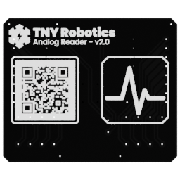
Useful links
Go to the Assembly Step
Go to the assembly step where the analog reader is being installed.
Board reference
Role
- receive commands from the control electronics;
- drive the joint motors;
- route position or feedback signals back to the controller;
- expose the connections needed by the locomotion system.
Location
The board is installed in the torso-backbone area, between the central electronics and the motor wiring.
Main topics
- 2 mm header connection to the backbone;
- a connector format distinct from the analog reader;
PCA9685PWM generation for the 14 motors at 200 Hz;- motor command and power paths;
- the two remaining PWM channels exposed on backbone extension headers;
- revision-specific pinout.
Poka-yoke mounting
The motor driver and analog reader use different connector formats when they mount to the backbone. One connector uses a 2x4 arrangement instead of 2x5, preventing the wrong board from being installed in the wrong position.
PWM channels
The PCA9685 drives the robot's 14 motors at 200 Hz. Its two remaining channels are made available through extension headers on the backbone for future uses.
Status LED
The motor driver has an addressable LED that can indicate the state of this board independently from the other electronics.
Pinout
Add a photo of the board with numbered pins here, followed by the completed table:
| Pin | Connector or header | Signal | Destination | Notes |
|---|---|---|---|---|
| 1 | To be numbered | To be completed | To be completed | To be completed |
The firmware path is described in Locomotion and Hardware drivers.