Visor board
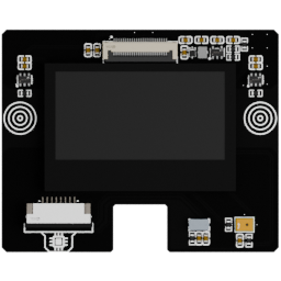
The visor board carries the head display, distance sensor, microphone, and capacitive buttons, and connects them to the main board.
Useful links
Go to the Assembly Step
Go to the assembly step where the analog reader is being installed.
Board reference
Role
- host the SSD1309 display directly on the PCB;
- provide the VL53L0X distance sensor;
- provide the PDM microphone;
- provide left and right capacitive buttons;
- route the connection to the main board.
Location
The board is installed in the robot's visor.
Main topics
- SSD1309 display;
- VL53L0X;
- PDM microphone;
- two capacitive button sensors;
- FPC connection to the main board.
FPC connection
The visor board connects to the main board through an 8-pin FPC with a 1 mm pitch.
Pinout
Add a photo of the board with numbered pins here, followed by the completed table:
| Pin | FPC or component | Signal | Destination | Notes |
|---|---|---|---|---|
| 1 | To be numbered | To be completed | To be completed | To be completed |
The firmware uses a common screen abstraction so that the display controller can vary between robot revisions. See Hardware abstraction.