Power board
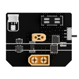
The power board is the entry point for the robot's electrical power path. It receives the battery supply, applies the available protection, and distributes power to the parts of the robot that need it.
Useful links
Go to the Assembly Step
Go to the assembly step where the analog reader is being installed.
Board reference
Role
The power board connects the battery input to the robot's protected power distribution system.
It switches the robot on, protects the main supply, and exposes the current-measurement connection used by the power-monitoring system.
Location
The board is installed in the rear power area of the torso.
Main topics
- XT60 battery input;
- power switch and MOSFET soft-start;
- reverse-polarity protection;
- XT30 output to the buck converter;
- mini fuse holder with a 20 A fuse;
- 2-pin JST-PH connection carrying the 5 V I2C
secondarybus to the INA219 current sensor.
Connections and protection
The battery connector is an XT60 located at the bottom of the board. The switch controls MOSFETs that provide soft-start behavior and protect against reverse battery polarity.
The main output is sent to the buck converter through an XT30 connector. A mini fuse containing a 20 A fuse provides a final protective interruption if a serious fault causes excessive current.
The board also exposes a 2-pin JST-PH connector carrying the high-level 5 V secondary I2C bus for the INA219 current sensor integrated on the power board.
Pinout
Add a photo of the board with numbered pins here, followed by the completed table:
| Pin | Connector | Signal | Voltage or current | Notes |
|---|---|---|---|---|
| 1 | To be numbered | To be completed | To be completed | To be completed |
Power safety
Disconnect the battery before inspecting or modifying the power board. Always verify the board revision and connector orientation before reconnecting power.
For the global power path, see Electrical architecture. For battery selection and mounting, see Battery guide.