Backbone
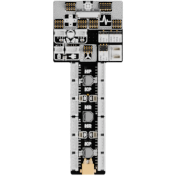
The backbone is the central connection board for the torso electronics. It brings together power, buses, and subsystem connections so that the robot can be assembled as a coordinated electrical system.
Useful links
Go to the Assembly Step
Go to the assembly step where the analog reader is being installed.
Board reference
Role
The backbone links the main processing electronics with the motor driver, analog reader, IMU board, power system, extension board, and ear motors.
Location
The board is located in the torso-backbone area.
Main topics
- power and ground distribution;
- 2 mm headers for the motor driver, analog reader, and IMU board;
- JST-PH 3P connectors for the two ear motors;
- connections to the power board and extension board;
- the motor-power corridor;
- the right-side expansion area.
Motor-power corridor
The backbone contains a corridor where motor power, analog signals from the analog reader, and digital signals from the motor driver run alongside one another. The power and signal routing is designed around the robot's physical layout, while the logic supply reaches the backbone through the quieter 5 V path from the extension board.
Expansion area
The right side of the backbone exposes:
- two connectors compatible with StemmaQT and Qwiic modules;
- a header for the
secondaryI2C bus; - a header for NeoPixel LEDs;
- two headers for the two unused PWM channels of the motor driver.
Head connection
The backbone connects to the main board through a 14-pin FPC with a 1 mm pitch.
Pinout
Add a photo of the board with numbered pins here, followed by the completed table:
| Pin | Connector or header | Signal | Destination | Notes |
|---|---|---|---|---|
| 1 | To be numbered | To be completed | To be completed | To be completed |
See Electrical architecture for the global buses and Hardware abstraction for the firmware configuration that selects them.