PCB ecosystem
The TNY-360 uses several printed circuit boards distributed through the head, torso, back, and feet. Together, these boards distribute power, connect buses, drive the motors, read sensors, and expose the robot's user-interface hardware.
This page is the overview and navigation hub for the complete PCB reference.
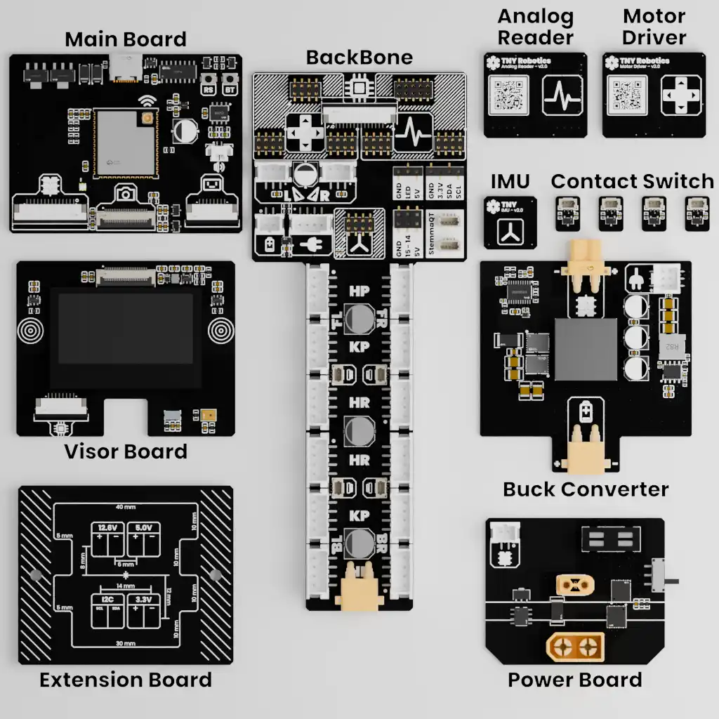
Overview of the TNY-360 PCB ecosystem.
Board layout overview
Power board
Follow battery input, protection, and power distribution.
Buck converter
Understand the regulated voltage rails used by the electronics.
Extension board
See how the extension ports connect to the backbone and the rest of the robot.
Backbone
Explore the central torso board and its connections to the other subsystems.
Main board
Discover the main processing and control electronics.
Visor board
Learn how the head display, sensors, and related signals are connected.
Motor driver
See how the robot's 14 motors are controlled from a central controller.
Analog reader
Understand how position feedback and ground detection signals are read.
IMU board
Explore the inertial sensor and its bus connection.
Contact switches
Learn how the four Hall-effect contact switches detect contact at the feet.
How the boards work together
The boards form a connected ecosystem rather than a collection of isolated circuits:
The exact physical connections and revision-specific pinouts belong to each board page. Begin with Electrical architecture if you need the global power and bus model first.
Check the board revision - QR Code
Connector numbering, components, and pinouts can change between PCB revisions. Always verify the revision before wiring or troubleshooting a board.
You can find the revision printed on the board itself, or scan the QR code on the back of the robot to be directed to the appropriate documentation page for your revision.