Contact switches
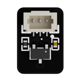
The four contact switches detect when a foot is pressed against the ground. Each switch combines a magnet in the foot with a Hall-effect sensor connected to the robot's analog-reading system.
Useful links
Go to the Assembly Step
Go to the assembly step where the analog reader is being installed.
Board reference
Role
- detect foot compression and ground contact;
- expose GND, VCC, and IO through a JST-SH 3P connector;
- send contact signals to the analog reader;
- provide information that can support gait control, stabilization, and diagnostics.
Location
The switches are installed in the four leg zones, in the motor corridor, with their wiring connected to the torso electronics.
Main topics
- Hall-effect sensor and magnet placement;
- 3.3 V supply and filtering;
- JST-SH 3P wiring;
- analog readout path through the analog reader;
- revision-specific pinout.
Electrical connection
The switches run from the 3.3 V bus generated on the main board. Filters on this bus remove most of the interference generated by the motor corridor before it reaches the contact switches.
The IO signal is read by the analog reader and then sent to an ESP32-S3 ADC input in the same way as the motor position-feedback signals.
Pinout
Each contact switch uses a JST-SH 3P connector:
| Pin | Signal | Function |
|---|---|---|
| 1 | GND | Ground |
| 2 | VCC | Filtered 3.3 V supply |
| 3 | IO | Hall-effect sensor output |
The mechanical design of the feet is described in Feet design. The software use of contact information is described in Locomotion.