The Laser sensor
This one's pretty much the same as the screen, since it's also an I2C component :)
The connection
The laser sensor uses the same 4-pin JST-PH connector as the screen, so the connection is the same as well.
We recommend a length of around 5cm to 10cm for this cable, to have enough slack to connect the laser easily,
but not too much to avoid having a lot of excess cable inside the head.
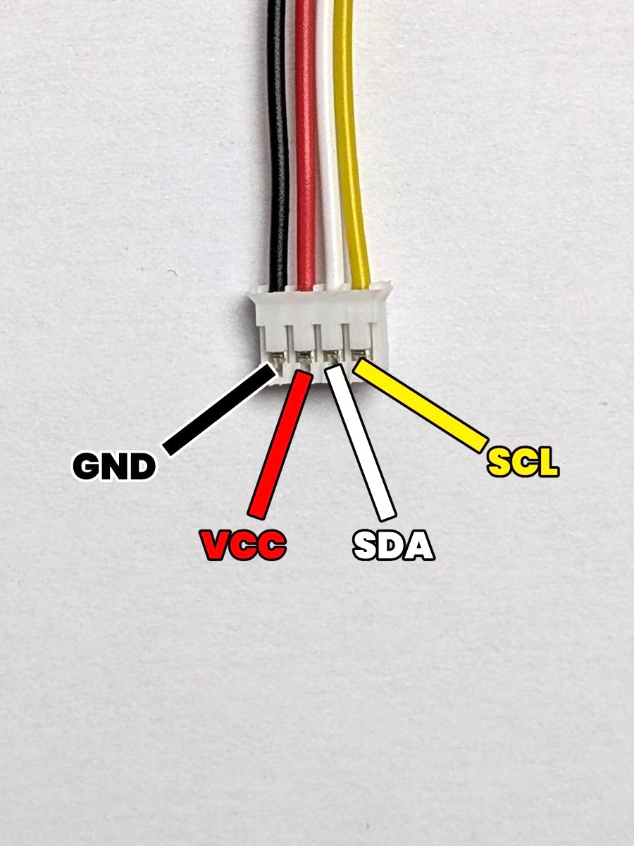
Here's a reminder of the pinout of the 4-pin JST-PH connector, as always:
- GND: The ground. (which is the pin most to the left)
- VCC: The power supply. (which is the second pin from the left)
- SDA: The data line. (which is the third pin from the left)
- SCL: The clock line. (which is the pin most to the right)
The result
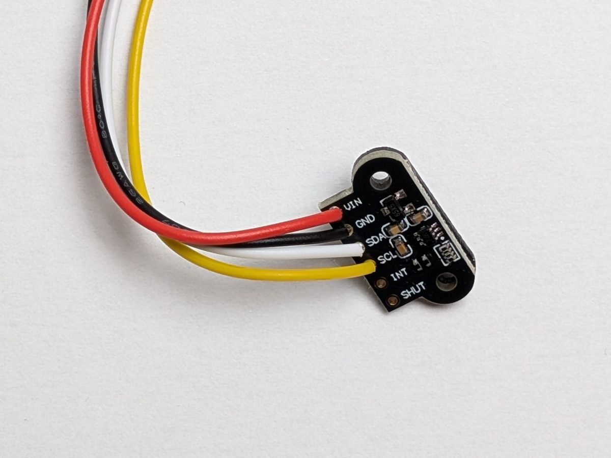
Here's what the connection should look like after soldering the JST-PH connector to the laser sensor:
As for the screen before, the laser sensor pin order is VCC, GND, SDA, SCL,
which is different from the JST-PH connector pin order GND, VCC, SDA, SCL.
So we swapped the GND and VCC wires to match the pinout of the laser sensor.
This one is done too ! Let's solder the last I2C component : the IMU !