Soldering the PCBs
In this part, we'll be soldering the SMD components required for the MG996R's custom PCBs.
This part is pretty straightforward if you already soldered the other PCBs of the robot.
Components list and placements
The custom PCB has only 2 simple components to solder :
| ID | Component | Quantity |
|---|---|---|
| 1 | SC-70-5 OPA333 Operational Amplifier | 1 |
| 2 | 0402 100nF Ceramic Capacitor | 1 |
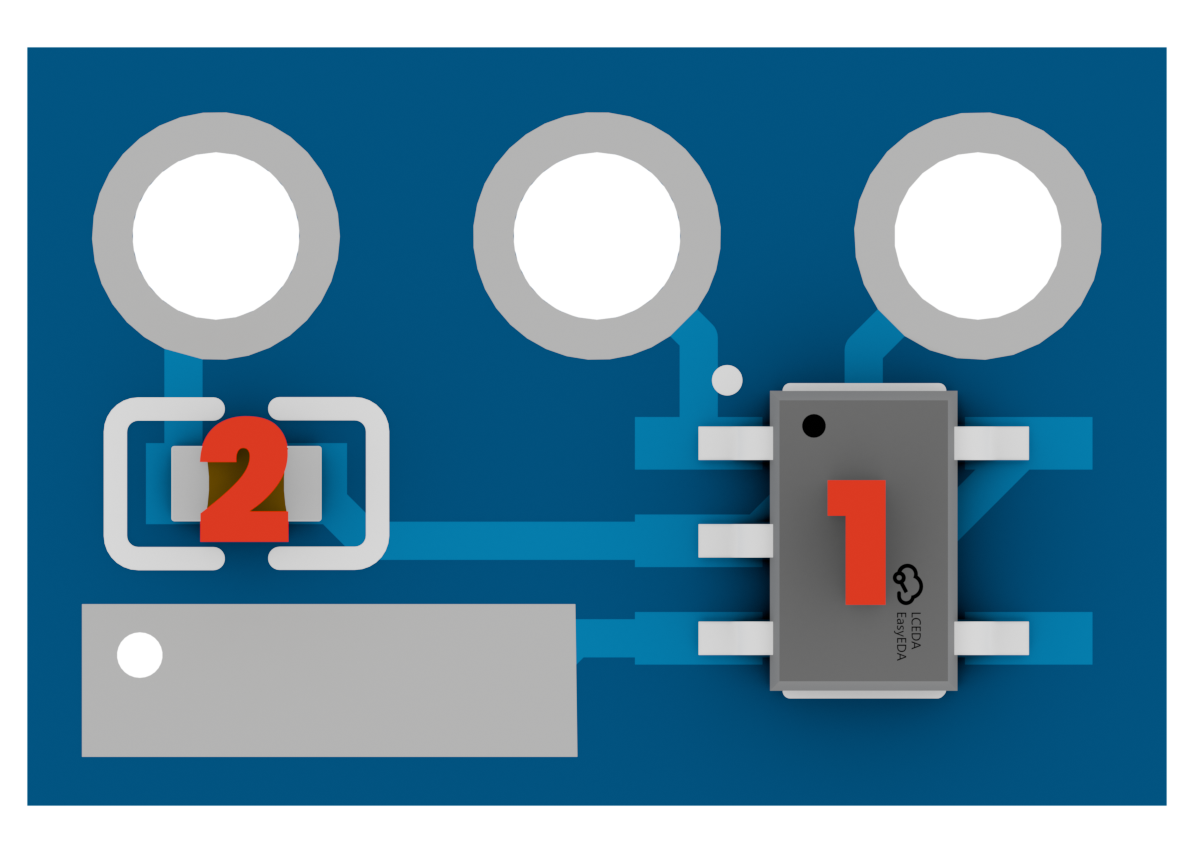
Pay attention to the pins of the OPA333 IC, as they are really small and you can easily make solder bridges between them if you put too much solder on the pads.
Holes order
The PCB has 3 holes that are designed to be soldered directly on the motor's potentiometer pins.
Since the Board is small, we couldn't put any silkscreen on it, so here is the order of the holes :
- VCC
The left hole is the VCC pin, which gets the power supply for the IC. - SIG
The middle hole is the signal pin, which connects to the potentiometers's output. - GND
The right hole is the ground pin, which connects to the motor's ground.
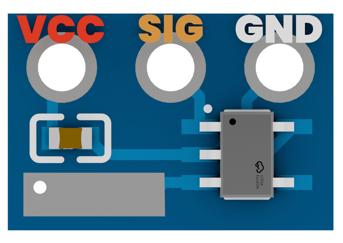
There's a big pad on the bottom of the PCB. This pad is the output of the PCB, which will be used to get the feedback out of the motor.
Inverted MG996R motors
We won't say this enough :
Depending on the manufacturer of your MG996R motors, the order of the pins of the potentiometer might be inverted :
- The VCC pin might be on the right instead of the left.
- The GND pin might be on the left instead of the right.
The only way to know for sure is to check continuity between the pins of the potentiometer and the motor's ground and power supply, using a multimeter.
If your motors are inverted, you'll have to solder the PCB upside down.
Final result
Here's what the custom PCBs should look like once the components are soldered on them :
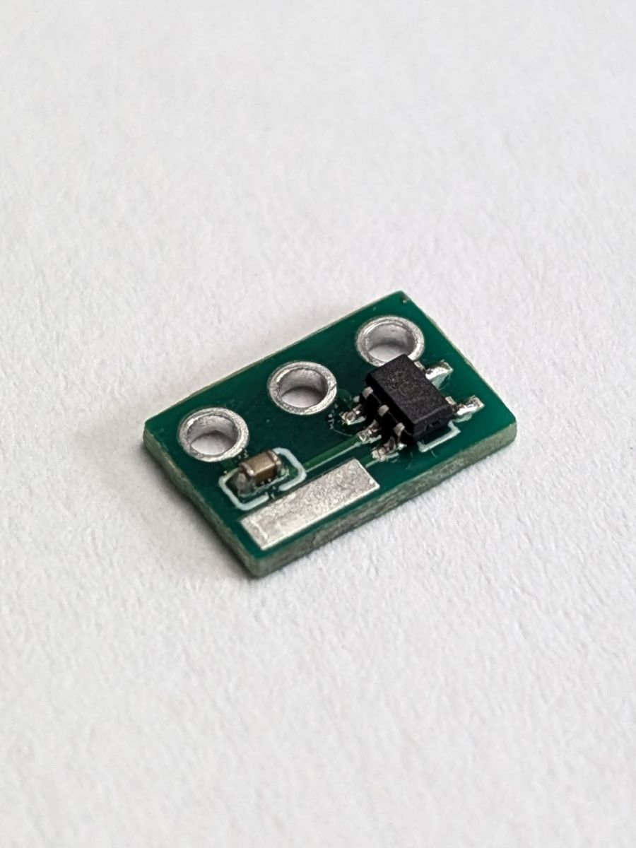
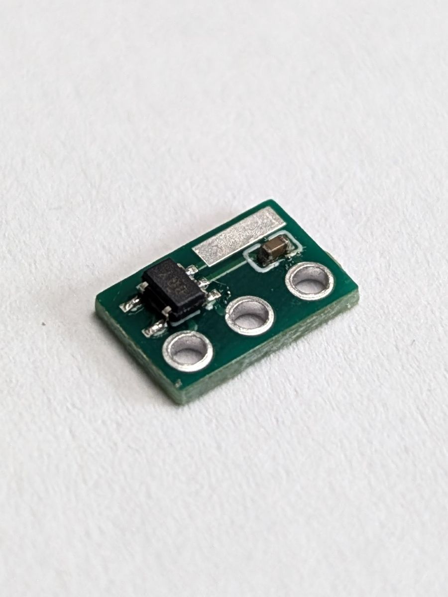
Since the robot uses 12 motors, you'll have to solder 12 PCBs :)
Once that's done, we can move on to the next step : Adding the custom PCBs !