Adding the custom PCBs
Now that the 12 custom PCBs are soldered, we can place them on the motors to get the feedback out of them !
Here's how to do it !
Types of motors
The TNY-360 has 3 "types" of motors, which is essentially just question of wire length and placement on the motors :
- Top Motors (T)
The robot uses 8 "top motors", which are used for the Hip-Roll and Hip-Pitch joints. These motors have 10cm long wires, coming out of the top of the motor.
- Left motors (L)
The Knee-Pitch joint of the left legs are powered by 2 "left motors", which have 30cm long wires, coming out of the left side of the motor.
- Right motors (R)
The Knee-Pitch joint of the right legs are powered by 2 "right motors", which have 30cm long wires, coming out of the right side of the motor.
Depending on the type of motor you are making, the way you place the wires inside them will be slightly different (oriented towards the wires exit), but the process is essentially the same for all of them.
Adding the PCBs
Well, let's start modifying these motors !
For each motor, you'll need these components :
| Component | Description | quantity |
|---|---|---|
| Custom PCB | The custom PCB that we soldered in the previous step. | 1 |
| MG996R Motor | The motor that we are modifying. | 1 |
| JST-XH 4-Pin Connector | A 4-pin JST-XH wire, with one side stripped. Length should be 10cm for Top Motors, 30cm for Left and Right Motors. | 1 |
Step 1 - Open the motor
The first step is to open the motor. This is pretty simple since you just need to unscrew the 4 screws on the back of the motor.
Keep it together!
A servomotor has 3 parts :
- The middle one housing the motor and the potentiometer;
- The front part with the gears and the output shaft;
- The back part with the PCB and the wires.
The 4 screws you unscrewed are holding all these parts together. So, make sure to keep the front and middle parts together, otherwise the gears might fall out and you'll have to get your hands dirty to put them back together!
Step 2 - Remove the old wires
MG996R motors use 3-pin Dupont (arduino) connectors. Since we want to use a 4-pin JST-XH connector, we need to remove the old connector's wires to replace them later with the new ones.
To remove the old wires, use a soldering iron and heat the pads on the motor's PCB where the wires are soldered, and gently pull the wires out.
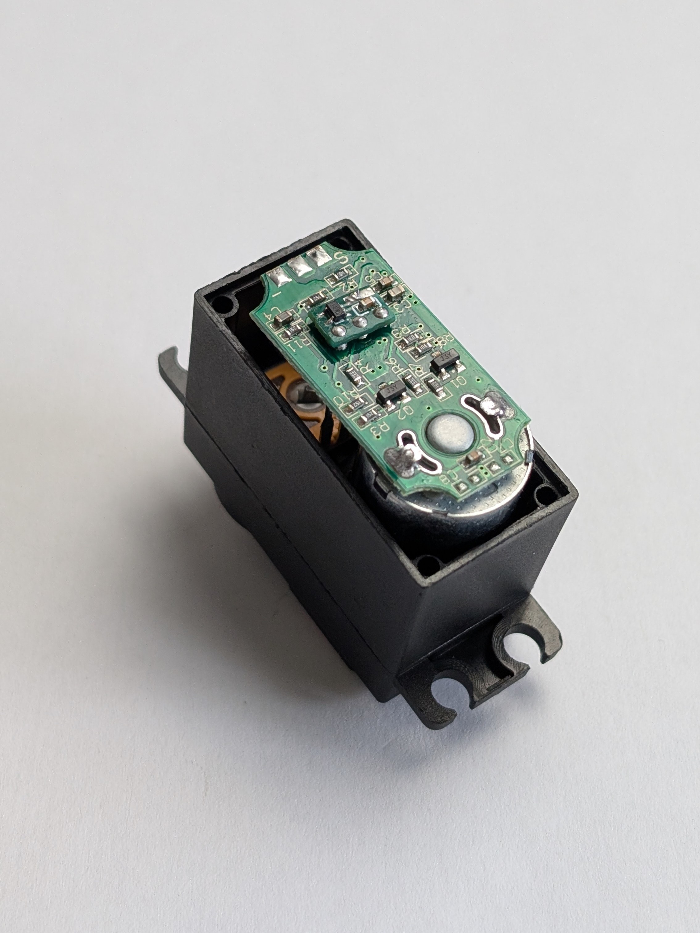
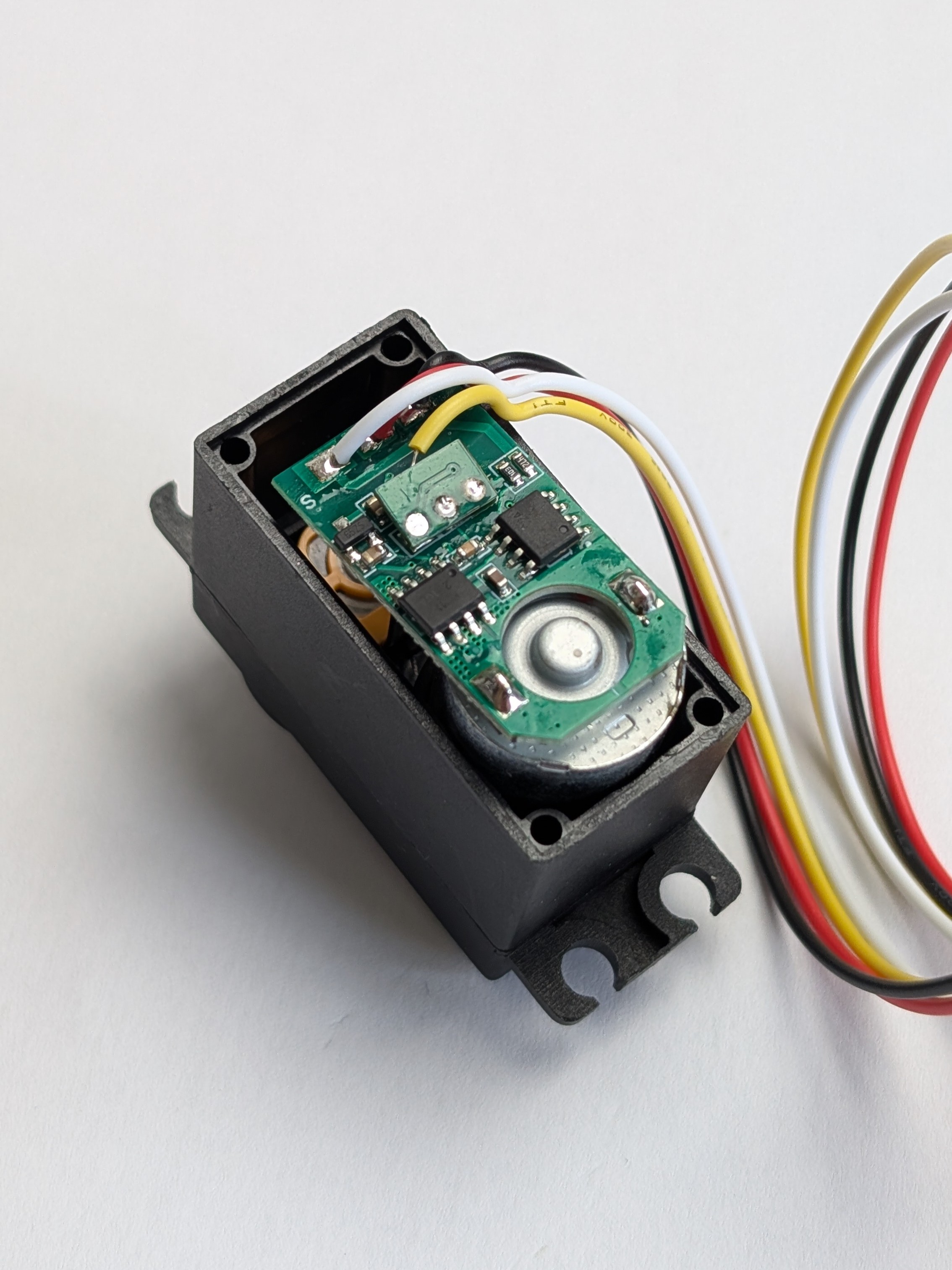
Step 3 - Check the potentiometer pins order
At this point you should have a clear view of the PCB of the motor, with 3 pins around the center. These are the pins of the potentiometer, which we will use to get the feedback out of the motor.
Before we solder the custom PCB on the motor, we need to check the order of these pins, since it can be different depending on the manufacturer of your MG996R motors.
This MG996R has the potentiometer pins in the "normal" order.
So we can solder the custom PCB upside up.
This MG996R has the potentiometer pins in the "inverted" order.
So we need to solder the custom PCB upside down.
To determine the order of the pins, use a multimeter to check continuity between the pins of the potentiometer and the motor's ground and power supply.
This will allow you to identify which pin is the VCC, which one is the GND, and which one is the signal pin.
If this order differs from the one we described in the previous section, then you have "inverted" motors, and you'll need to solder the custom PCB upside down.
Step 4 - Solder the custom PCB on the motor
Once you know the order of the pins, you can solder the custom PCB on the motor.
Place the 3 holes of the custom PCB on the 3 pins of the potentiometer, and use a soldering iron with solder and flux to solder it in place.
Be careful!
Make sure the custom pcb's pad (which are on both sides of the PCB) doesn't touch any of the motor's components !
Use some insulating tape between the motor's PCB and the custom PCB to make sure they don't touch each other.
Step 5 - Solder the JST-XH connector
Now that the custom PCB is soldered on the motor, we need to solder the JST-XH connector to the custom PCB to be able to connect it to the main board later.
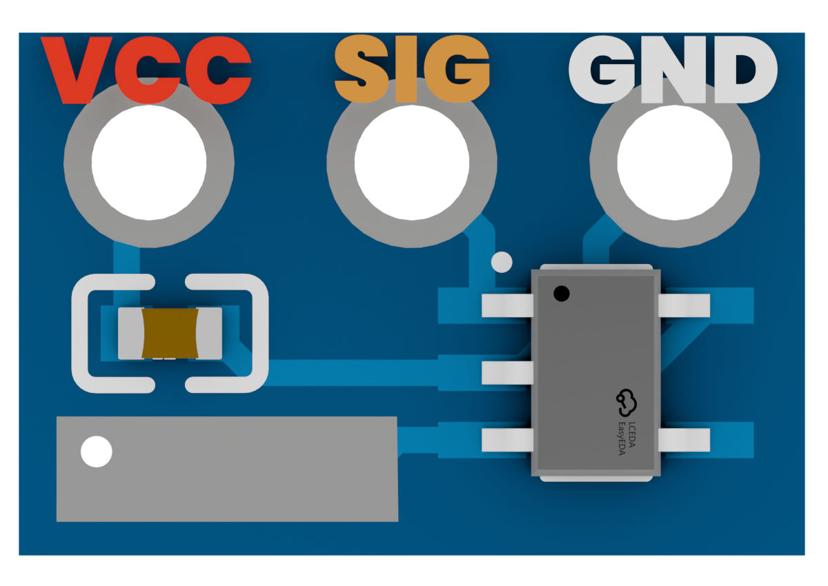
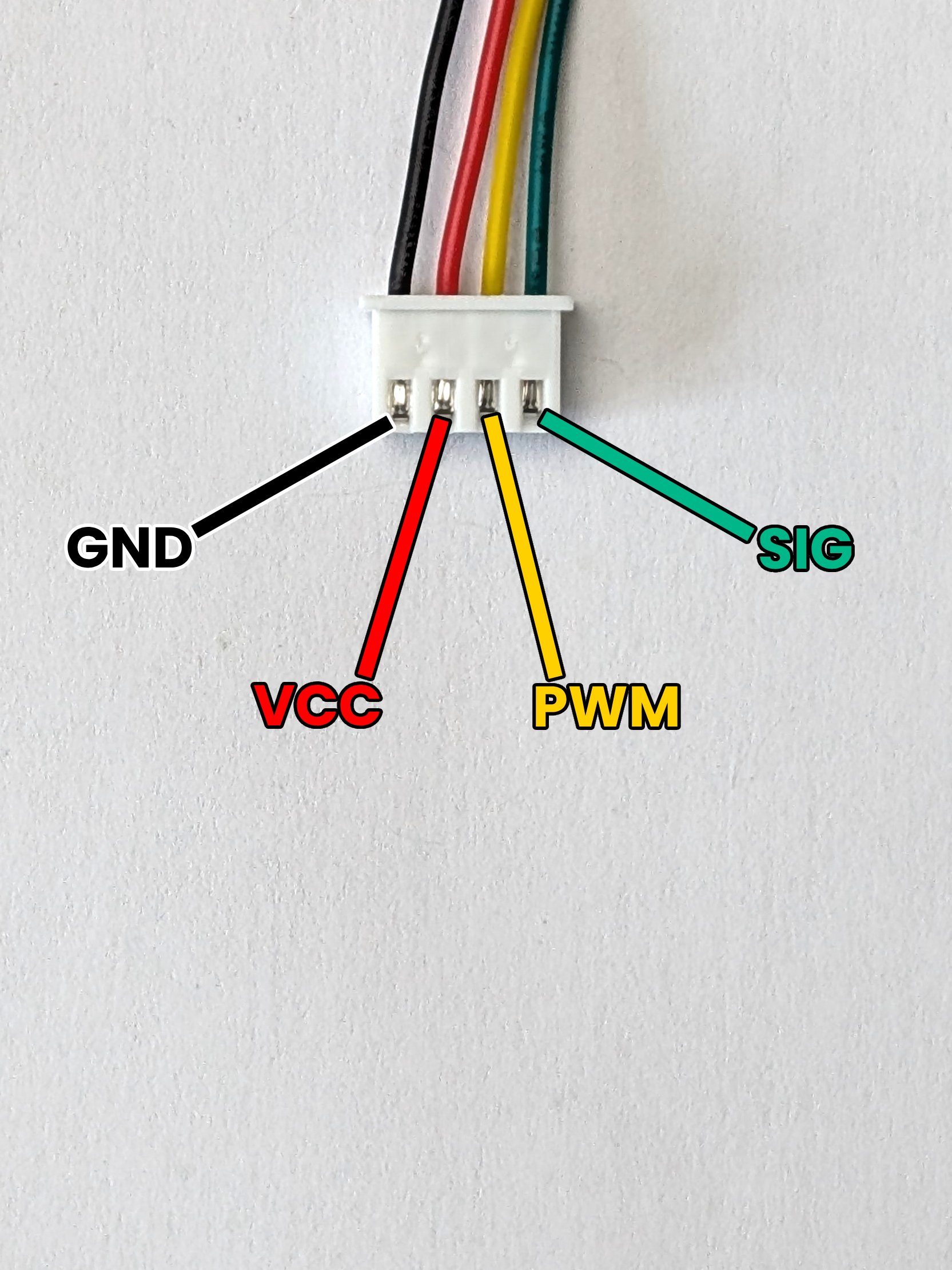
Here's the pinout of the JST-XH connector that you need to solder on the custom PCB :
- GND : The ground connection.
- VCC : The power supply for the motor.
- PWM : The pwm signal to control the motor.
- SIG : The feedback signal from the custom PCB.
Keep in mind that the order of the pins is the important part here, not the color of the wires, since the color can be different depending on the manufacturer of the JST-XH connectors.
Make sure to solder the wires in the correct place, as soldering them in the wrong place can damage (or even destroy) the custom PCB and the motor !
Top motors cover
If you are making a Top motor, make sure to put the connector through the hole on the back cover of the motor, BEFORE soldering it on the custom PCB!
The cover of the top motors cannot be put back in place if the connector is soldered on the PCB before putting it through the hole!
Wire orientation
Depending on the type of motor you are modifying, you may want to orient the wires in a specific way to make sure they exit the motor in the right direction and with the same length.
Keep in mind :
- The Left motors should have the wires exiting on the left side of the motor.
- The Right motors should have the wires exiting on the right side of the motor.
- The Top motors should have the wires exiting on the top of the motor.
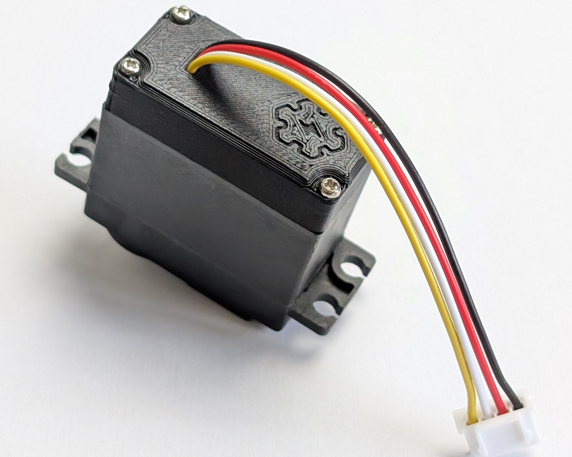
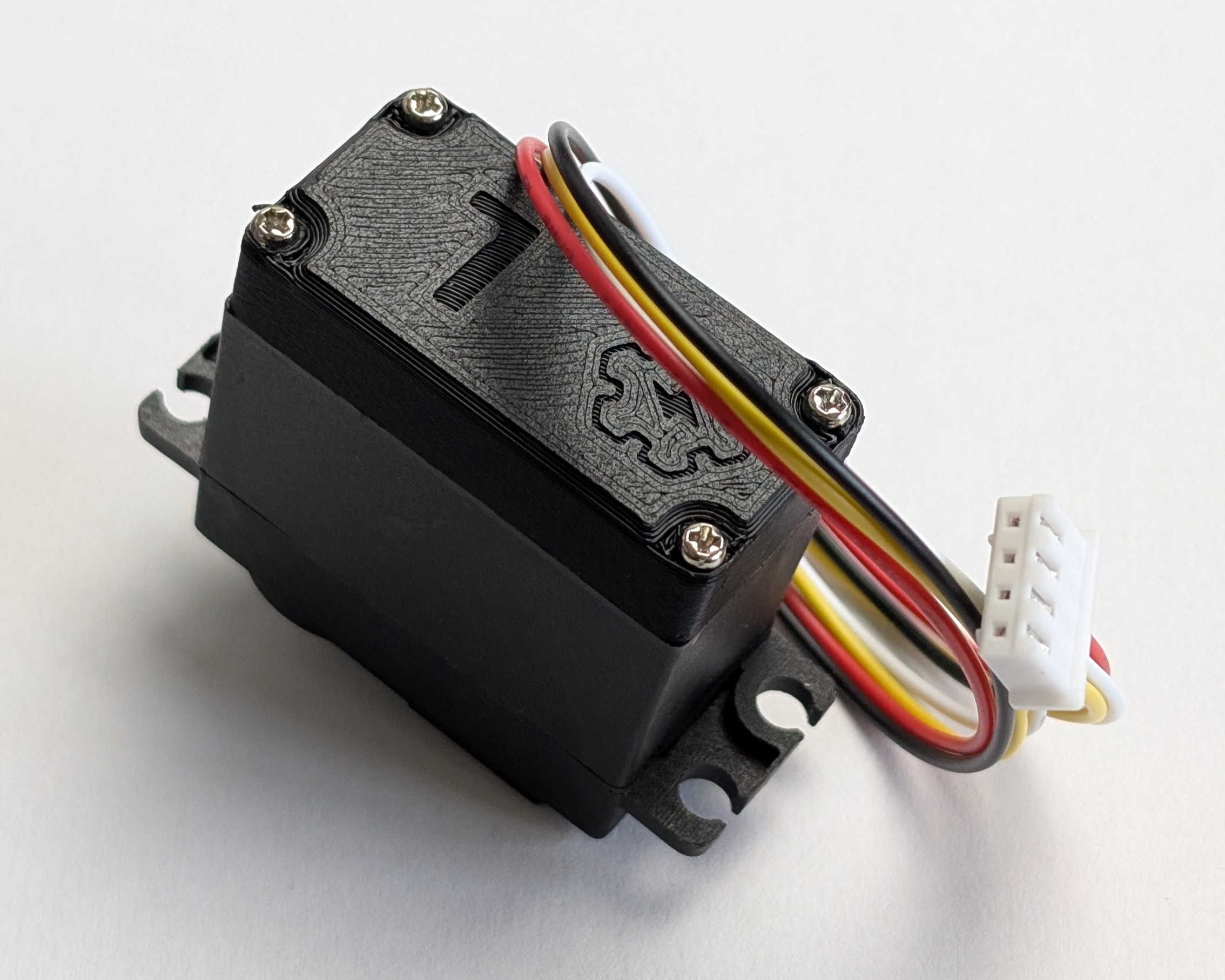
Here's pictures of the motors fully soldered with the wires oriented in the right way :
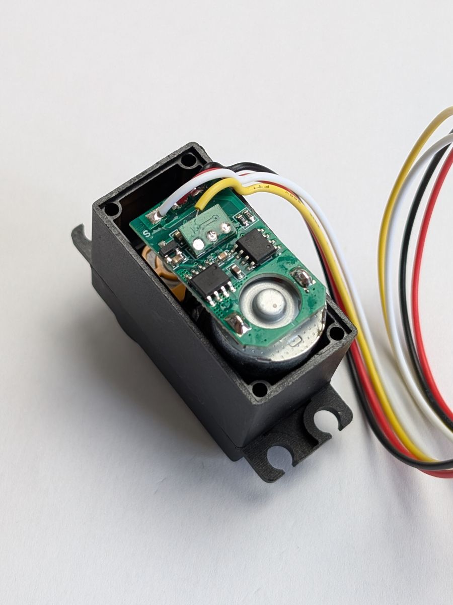 The Left Motor
 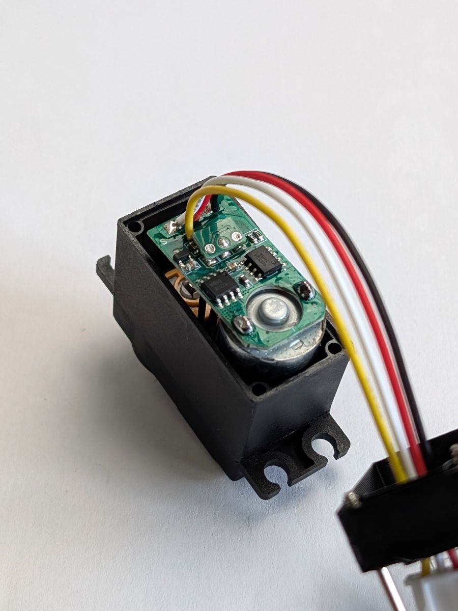 The Top Motor
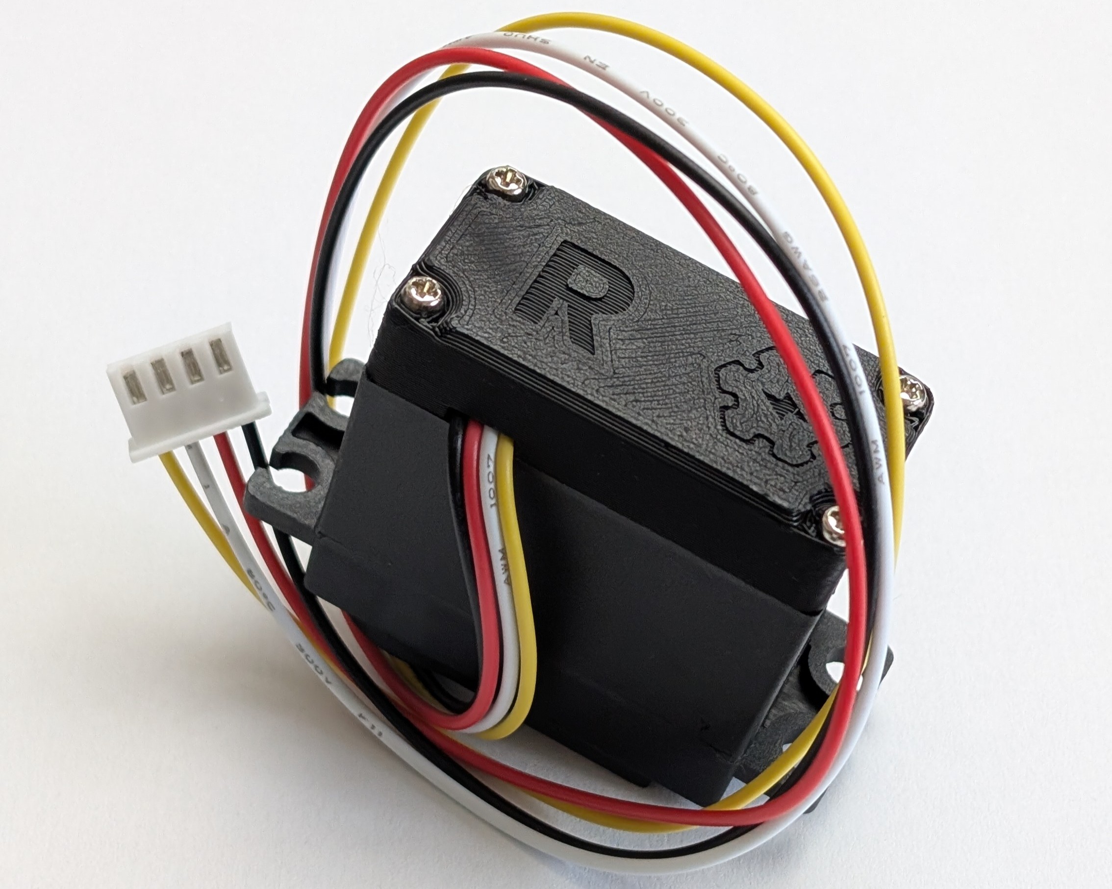
 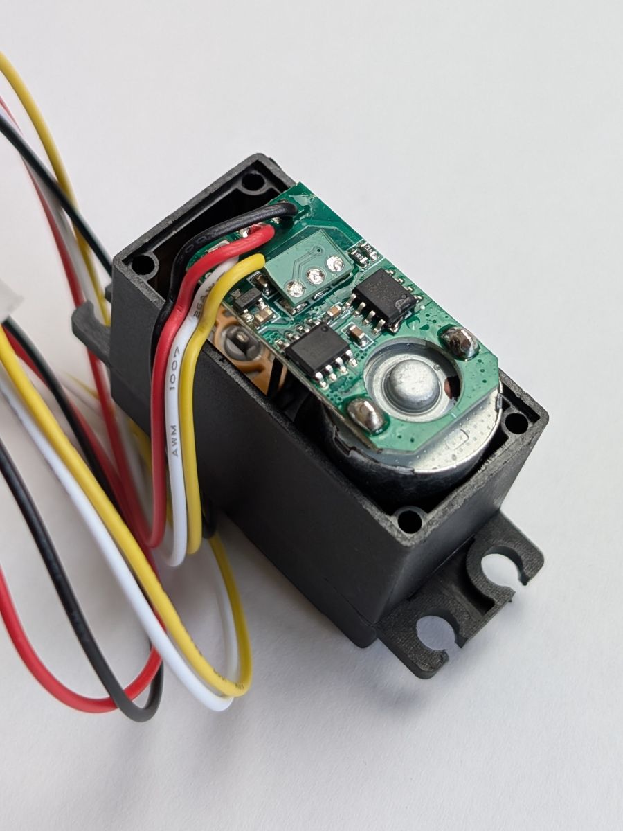 The Right Motor
 Step 6 - Close the motor
Now that everything is soldered, you can close the motor by putting the Custom Back Cover in place and screwing the 4 screws back in!
Use the right cover for each type of motor, since the holes for the wires are in different places for the Left, Right and Top motors.
For the Left and Right motors, make sure to give some slack to the wires inside the motor, so that they don't get pulled when you close it.
All the motors are modified ? Congratulations! You just unlocked one of the best features of the TNY-360 !
Let's quickly flash the firmware on the main board and assembly this thing, now!