The Screen
After soldering the buttons, it's time to solder our first I2C component: the screen!
The connection
This connection is pretty straight forward too, but we'll use a JST-PH 4-pin connector.
Since the screen is justn in front of the Main PCB, we recommend a length of around 5cm to 10cm for this cable,
to have enough slack to connect the screen easily, but not too much to avoid having a lot of excess cable inside the head.
Here's a reminder of the pinout of the 4-pin JST-PH connector:
- GND: The ground. (which is the pin most to the left)
- VCC: The power supply. (which is the second pin from the left)
- SDA: The data line. (which is the third pin from the left)
- SCL: The clock line. (which is the pin most to the right)
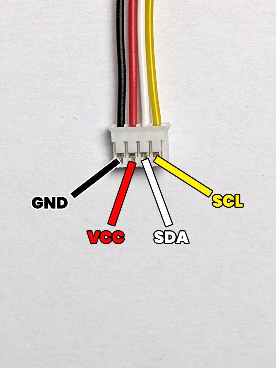
Depending on the supplier you ordered the screen from, the pinout of the screen might be different (VCC and GND might be swapped, or SDA and SCL might be swapped).
Make sure to double-check the pinout of your screen before connecting it !
The result
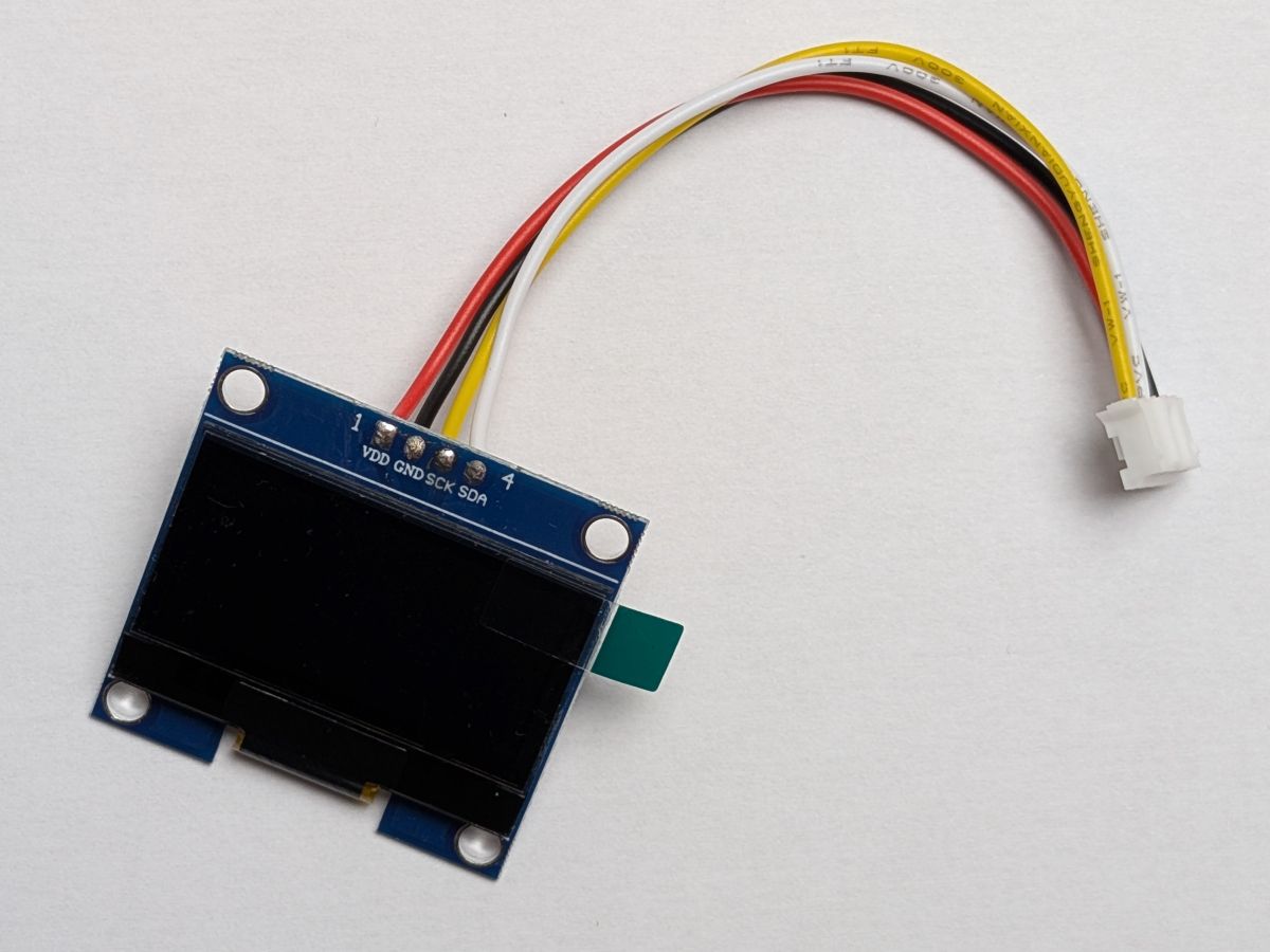
Here's what the connection should look like after soldering the JST-PH connector to the screen:
As you can see on the picture, the screen pin order is VCC, GND, SDA, SCL,
which is different from the JST-PH connector pin order GND, VCC, SDA, SCL.
In this example, we made sure to swap the GND and VCC wires to match the pinout of the screen, so that the connections are correct.
Removing the default header
Depending on the supplier you ordered the screen from, it might come with a default header soldered to it.
If that's the case, you can remove it by first pulling the plastic part of the header with a pair of pliers, and then desoldering the remaining pins from the screen with a soldering iron and a desoldering pump or some desoldering braid.
All good ? Great! Let's solder the laser sensor next !