The IMU
The IMU (Inertial Measurement Unit) is the last I2C component we'll solder in this section.
The connection
The IMU uses the same 4-pin JST-PH connector as the screen and the laser sensor, but we recommend a length of at least 20cm. This is because the IMU is located in the center of the robot's torso, and needs to connect to the main board in the head.
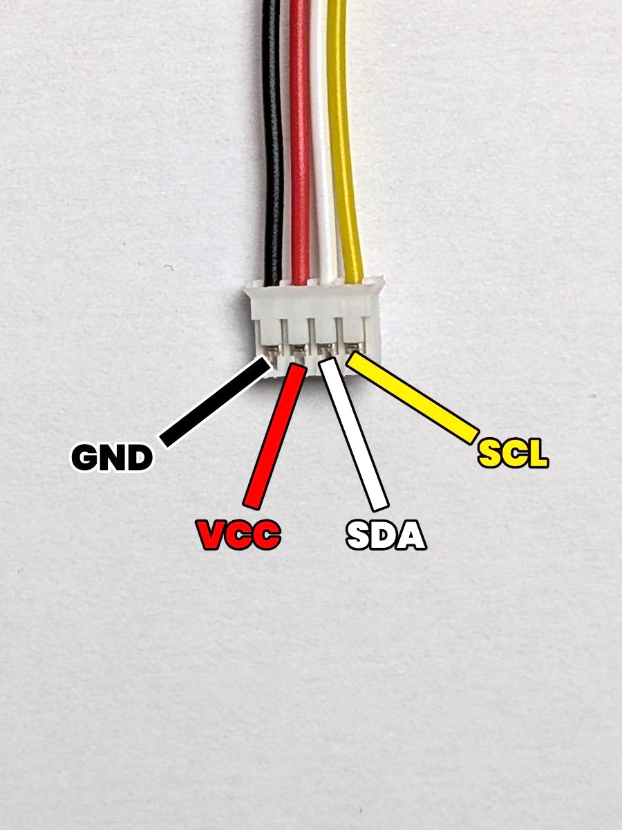
Little reminder of the pinout of the 4-pin JST-PH connector:
- GND: The ground. (which is the pin most to the left)
- VCC: The power supply. (which is the second pin from the left)
- SDA: The data line. (which is the third pin from the left)
- SCL: The clock line. (which is the pin most to the right)
The result
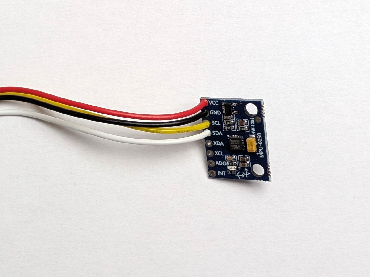
Here's what the connection should look like after soldering the JST-PH connector to the imu:
We've seen for the screen and the laser sensor that the pin order of the components could be different from the JST-PH connector pin order,
and this is the case for the IMU as well, since its pin order is VCC, GND, SCL, SDA.
In this case, we made sure to swap the GND and VCC wires, as well as the SCL and SDA wires, to match the pinout of the IMU.
Nice, all done with the I2C components ! Let's move on to the microphone (which is a bit harder, sorry in advance) !