The Microphone
The Microphone uses I2S (and not I2C!) to communicate with the main board, which means that it uses a different connector (JST-PH 5-pin).
The connection
The Microphone uses a 5-pin JST-PH connector, which has a whole different pinout from the 4-pin JST-PH connectors we've been using.
Since this micrphone is located in the head next to the main board, we recommend a length of around 5cm to 10cm for this cable,
to keep the excess cable to a minimum, while still having some slack to connect the microphone easily.
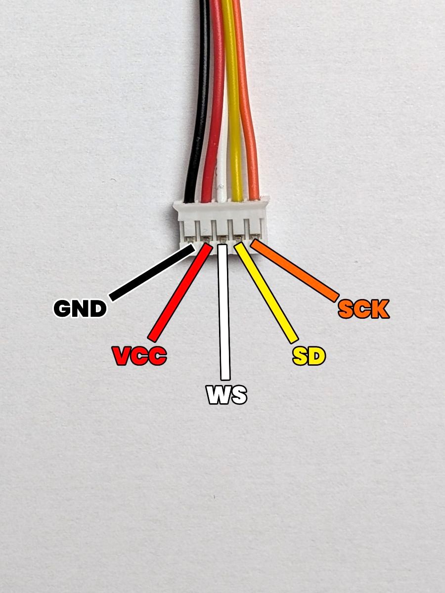
Little reminder of the pinout of the 5-pin JST-PH connector:
- GND: The ground. (which is the pin most to the left)
- VCC: The power supply. (which is the second pin from the left)
- WS: The word select line. (which is the middle pin)
- SD: The data line. (which is the second pin from the right)
- SCK: The clock line. (which is the pin most to the right)
If you look at the pins of the microphone, you'll see an other pin called L/R (Left-Right). This pin is used to select the left or right channel of the microphone, but since we only use a mono output, we'll connect this pin to the GND pin of the connector to force the microphone to use a single channel.
The result
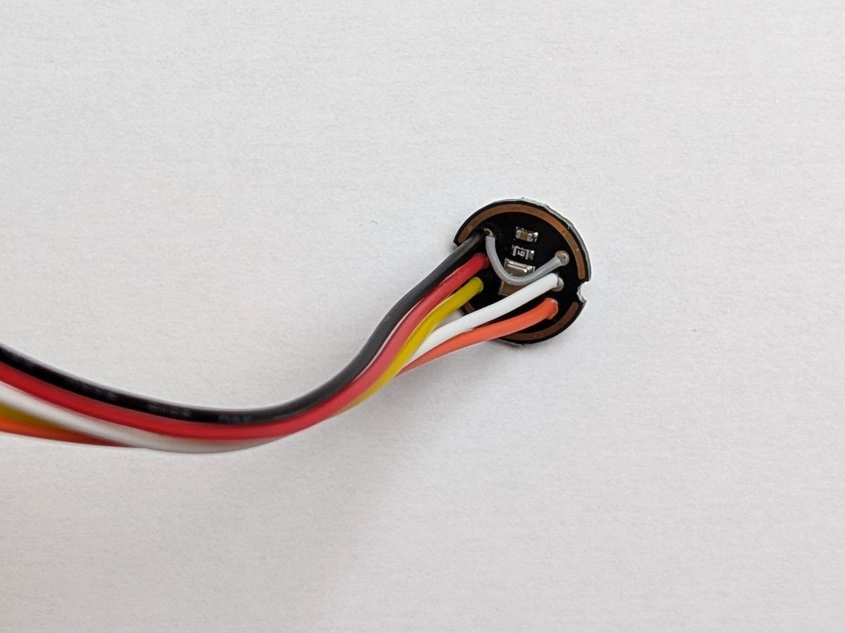
Here's what the connection should look like after soldering the JST-PH connector to the microphone:
As you can see on the picture, the two top pins (GND and R/L) of the microphone are connected together using a small jumper wire.
Don't leave the R/L pin unconnected! If you do, the microphone will switch randomly between the left and right channels, which will cause the microphone readings to be very unstable and noisy.
Okay, now that all the components have their connectors soldered, let's make some custom cables !