Preparing the components
Now that you've soldered all the PCBs, it's time to get all the other components ready for assembly.
In this part of the guide, you'll see how to solder the microphone, screen, and other components of the robot to their cables.
Cable order and connectors
After soldering everything, we need to talk a bit about the connectors, cables, and the order of their pins. This is important to avoid any confusion (or, worse, any damage) when connecting the components to the PCBs.
Pin order
Pay close attention to the pin order of the connectors and cables!
If not connected properly, you might damage the components or the PCBs in irreversible ways (you don't want to see that magic smoke).
Always double-check the pin order and the connections before soldering anything and powering on the robot.
If you have any doubts about the pin order or something else, please come talk to us on the Discord server before proceeding.
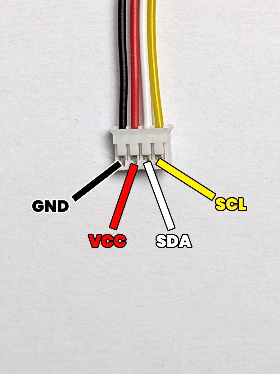
JST-PH - 4 Pins connector
This is a 4-pin JST-PH connector, which is used in the robot for connecting I2C devices using 4 wires:
- GND: The ground. (which is the pin most to the left)
- VCC: The power supply. (which is the second pin from the left)
- SDA: The data line. (which is the third pin from the left)
- SCL: The clock line. (which is the pin most to the right)
Pay close attention when soldering this cable to the components, and make sure to connect the right wires to the right holes of each component.
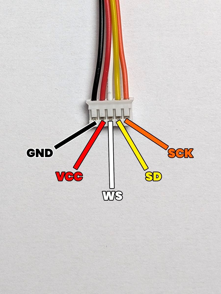
JST-PH - 5 Pins connector
This is a 5-pin JST-PH connector, which is used in the robot for connecting I2S devices using 5 wires:
- GND: The ground. (which is the pin most to the left)
- VCC: The power supply. (which is the second pin from the left)
- WS: The word select line. (which is the middle pin)
- SD: The data line. (which is the second pin from the right)
- SCK: The clock line. (which is the pin most to the right)
Devices with a L/R (Left-Right) pin will have this pin connected to the GND pin of the connector to force a mono output.
Overview
Here's the components and boards you'll solder in this section :
- The Touch Sensors
You'll solder a JST-PH 3-pin connector to the pins of the two touch sensors. - The Screen
You'll solder a JST-PH 4-pin connector to the pins of the screen. - The Laser Sensor
You'll solder a JST-PH 4-pin connector to the pins of the laser sensor. - The IMU
You'll solder a JST-PH 4-pin connector to the pins of the IMU. - The Microphone
You'll solder a JST-PH 5-pin connector to the pins of the microphone. - The Feet Contact Wire
You'll create a custom cable for the feet contact switch. - The Paw Boards Wires
You'll solder the power wires for the two Paw Boards. - The Power Board Wires
You'll solder the power wires for the Power Board.
Ready to solder? Let's start with the buttons, then!